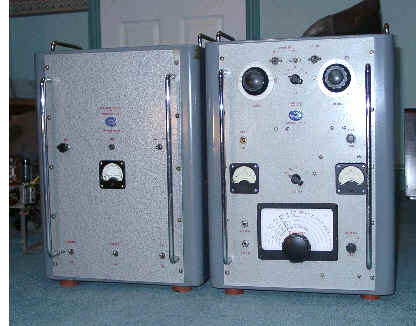
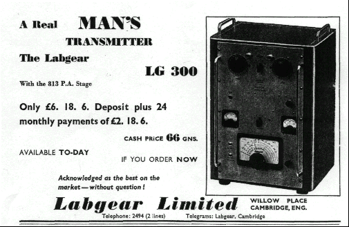
The Labgear LG300 5 band transmitter

by Ken Brooks G3XSJ

Settling down for a winter reading of 1950’s RSGB Bulletins, the image of a large and handsome piece of amateur radio equipment stared out from the front pages. For years and years this same piece of equipment appeared, symbolising the stability of the era. Even the captions were alluring with scripts likeA real man’s transmitter.” The haunting image was in fact the Labgear LG300, a chunky, classically designed 150 watt rig in a steel cabinet with chrome handles giving it a very businesslike appearance.

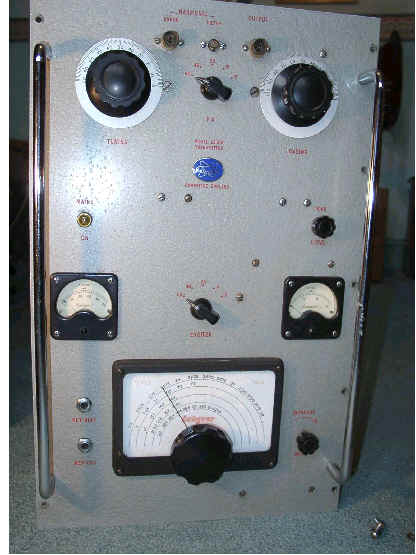
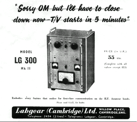
Adverts for the LG300 first appeared in the RSGB Bulletin in January 1955, illustrating what was presumably their prototype which had round meters. By March 1955 the price had been revealed as 47gns, (£49.35), less 813 valve. Much emphasis was placed on the TVI proofing of the instrument. This was in the days of rapid TV growth, and with transmissions on band 1, TVI was a real problem for amateurs. The September 1955 Bulletin advert played on those fears with the eye catching caption Sorry OM but I’ll have to close down now - T/V starts in 5 minutes” .

In January 1956 a photograph of the companion power supply and modulator first appeared, suggesting that its development might have been an afterthought. Skipping through the years, the final advert appeared in May 1961. The price was now 66 gns, (still less 813!), and a new address was given along with affiliation to the PYE group of companies. Presumably PYE marketing decided there were insufficient returns from advertising what was then becoming a time expired product.
Decades on, all of these adverts worked for me, and I decided to look for one of these transmitters. But what was inside that smart grey cabinet?

Description
The broad specification is a 150 watt CW transmitter covering the 80, 40, 20, 15 and 10 metre bands. An external power supply is needed, although a mains transformer is provided to supply the PA heater. An
external modulator is needed for AM.
The transmitter is a seven valve design using 5763’s for the VFO and multiplier stages, a KT66 clamp valve and an 813 PA. Keying can be either at the VFO or subsequent buffer stage. Labgear incorporated their Wideband Coupler in the LG300, a prefabricated band switched multiplier unit using four 5763’s. This provides sufficient drive for maximum legal input to the 813 PA. TVI precautions comprise a tunable series resonant trap on the RF output, and filtering of all power inputs.


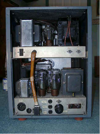
The Labgear LG300— PSU/Modulator on the left hand side, RF unit on the right


Band switching is accomplished at low level by wafer switches in the multiplier, and by a separate tank circuit switch. The tank circuit switch is of massive ceramic construction but spoiled by a fragile diecast detent mechanism. Considerable torque is need to overcome the detents. With two switches needed to select a band Labgear issued a cautionary note in their instructions warning users against multiplying in the PA.

Acquisition and rehabilitation
An advert placed in Radio Communication produced some encouraging responses and I effectively bought those offered over the phone. These varied from highly modified to original, and a further advert produced the circuit diagrams and instructions.
With all the information I set about running up the best example. Remember these are big beasts with lots of volts inside! Having made an inspection of the wiring, the rectifiers were removed and mains gingerly applied. This was accompanied by a very noticeable thump from the mains transformer, the heaters heated and all appeared well. Next, the VFO and exciter HT was applied and operation of the VFO was evidenced by an indication on the drive meter.

Tuning up
Feeling slightly less intimidated by this early success, the EHT was applied. Such confidence was misplaced however because the PA meter immediately swung about wildly and in sympathy with a very loud and worrying cracking sound from “somewhere inside.” I have a great deal of respect
for equipment containing high voltage supplies, and was not too keen on poking around inside a piece of equipment showing signs of imminent self destruction either. A very detailed power off study was therefore made of the EHT circuitry, and this revealed the loose solder tag screw that caused the trouble.

It had been noticed that drive levels varied between bands and before activating the PA it was expected that full RF output would not be obtained, but with EHT applied and when tuning up the pi network, the rig delivered the full 150 watts of RF into a dummy load. This could be easily exceeded at the expense of signal quality.
Running on transmit for even short intervals results in considerable heat build up within the PA compartment. The 813 heater dissipates 50 watts, there is a large screen resistor, and the anode dissipation all contribute to heating effects. Compared with modern equipment these are significant but typical losses for a device of this period.

I have not yet air tested it, mainly because of slothfulness on my part sorting out the transmit/receive arrangements, but its capability is not in doubt. Overall, the LG300 is a fascinating piece of equipment and I believe there are already a few in VMARS members’ hands. Despite its robust appearance some parts have a distinctly hand built look about them and there
are physical weaknesses in a couple of areas. With care, these can be overcome, and my limited experiences go to prove that 1950’s technology can be resurrected with relative ease.
In their time these were very expensive items of equipment and perhaps treasured possessions of their fortunate owners. They have probably survived because there is very little to go wrong that cannot be repaired. I look forward to running this one up and having real contacts using it, but to be completely authentic my radio room carpet should be replaced with lino, I should take to wearing a sports jacket with leather elbow pads, and I should take up smoking a pipe!

View of the PA compartment

Rear view of the PSU/modulator cabinet—plenty of heavy metal here!

This article and pictures copyright © Ken Brookes G3XSJ
and may not be reproduced elsewhere without permission.

HTML conversion Colin Guy G4DDI.