|
Replacing A Worn Out Rotary Converter in a 62 Set with A Solid-State DC to DC Power Supply By Simon Dabbs, G4GFN |
|
|
The Prologue
Background Then, one day the rotary converter started making strange noises and I could hear the revolutions, and see the HT voltage, dropping. Despite my best efforts with light oil to the bearings and a hint of Electrolube to the commutator, I decided the kindest act would be to retire the poor old thing and have a go at designing and building a solid state DC to DC converter to go in its place. I should point out at this stage that I am not a professional engineer, but a humble apothecar. Anyway, this is what I came up with; it worked for me, so I thought I’d write it up for the benefit of others whose gear might be suffering from old age in the rotary or vibratory PSU departments. Circuit Development |
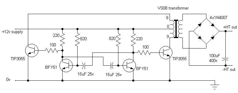
At this stage, I was delighted to measure about 360V AC off load. I then connected a 15W mains pygmy lamp, which lit to full brilliance with 260V AC measured. Quite encouraging. I then added a bridge rectifier and a 100µF smoothing capacitor. With a 3,900 ohm load, it achieved 270V DC, which is slightly down on the 320V target, but good enough. Installation The reason for choosing TIP3055s as opposed to 2N3055s is that they are well suited to bolting (with insulating kits and heat-sink compound) to the inside of the back of the chassis, each by means of one hole only. Testing All-ON was selected and once warmed up, transmit was tried on 1963kHz AM, monitoring on my AR88LF receiver. Good modulation was heard with just a trace of somewhat raspy hum. Indicated HT was 260V. Power out was measured at about 2W, slightly down on the 3W with the old rotary. The circuit was soak tested on receive for a few hours and held up well. There was little heat apparent in the vicinity of the power transistors. Overall, I am fairly satisfied with the results. I guess one key factor in the project’s success is the use of a toroidal transformer, which is compact and also has the advantage of not allowing much hum-inducing magnetic flux to escape. Presumably, using a 50Hz transformer, whilst being bigger than the higher frequency ones often seen in switch-mode power supplies, means that the low switching rate generates little RF hash. I am hoping that this modification will keep the set on the air for many years to come. |
Circuit diagram of the converter described above.
This article is copyright ©
2002 Simon Dabbs G4GFN
and may not be reproduced elsewhere without permission.
HTML conversion Colin Guy G4DDI